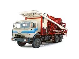
Mobile installations for development and research of oil and gas wells
The Mobile Well Test and Development complex is designed for test and development of oil and gas and gas condensate wells, for automatic metering of producing wells output at various pressures, fluid separation with further tank-truck loading and associated gas recovery (flaring). After metering the well production is gathered either into the field gathering system or into a local independent oil and water gathering system with further tank-truck removal.
The design provides for a system to have associated gas either fed to a gathering system or discharged to a flare. It is possible to use gas as fuel for oil heaters and gas power stations.
The installation can be used as a mini booster pump station or preliminary water discharge unit in exploratory wells and for trial operation of fields.
Specifications
Technical details
Basic sets of the equipment
The Mobile Well Test and Development complex comprises the following trailer-mounted or frame-mounted process equipment (see Fig.1):
1) test separator ;
2) storage tank ;
3) inlet manifold system;
4) flare unit ;
5) block of bottoms pump ;
6) Complete set of Connection Piping.
Additionally equipped with:
- bulk oil installation;
- power unit (diesel-gas power station);
- reagent metering unit;
- gas installation (propane, butane, inert gas);
- unit for heating well products;
- drainage tank with pump unit;
- mobile block boxing operator;
- bulk water installation;
- electric heating, thermal insulation of pipelines, apparatus and valves;
- Control Instrumentation: Sensors/Transducers, Actuators, Programmable Logic Controller and Control Cabinets located directly in process units.
An automated workstation of the operator serving the PKIOS complex is used to measure the well production rates, complete with a laptop in industrial design and an uninterruptible power supply unit for process automated control system.
The upper level of the instrumentation and сontrol system is responsible for ensuring data compatibility between the process facility and the automated control system. This Level includes an Operator’s Automated Work Station. The station provides a visual display of the process parameters, records selected process parameter conditions and generates reports in a graphic or plain text format, etc. The station is an essential tool enabling the Operator to control the process.
It is a package unit and comes fully assembled and ready for immediate use.
Fig. 1 schematic diagram with auto-removal of the studied fluid
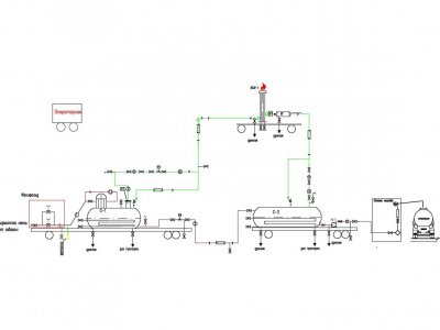
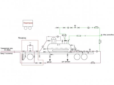
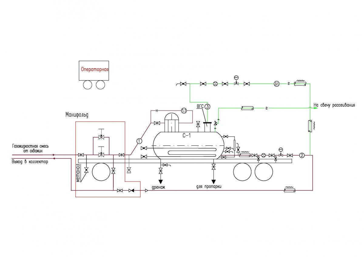
Fig. 2 schematic diagram operating in its own autonomous oil recovery system
The design provides for a system to have associated gas either fed to a gathering system or discharged to a flare. It is possible to use gas as fuel for oil heaters and gas power stations.
The installation can be used as a mini booster pump station or preliminary water discharge unit in exploratory wells and for trial operation of fields.
Specifications
Technical Data | |
| Process Fluid | Oil & Gas Well Stream (oil, gas, stratal water) |
| Capacity | |
| - for liquids, m3/day | from 1 to 500 (or higher if requested by Customer) |
| - for gas, nm3/day | From 1000 to 200 000 |
| - error in metering liquid mass flow rate | Metering accuracy ± 2.5 mass. |
| - error in metering volumetric gas flow rate | Metering accuracy ± 5% |
| Inlet pressure (design), MPa | 1,6; 2,5; 4,0; 6,3; 10,0; 16,0 |
| Ambient temperature, 0С | from -60 to +50 |
| Service durability, no less than, years | 10 |
Technical details
Basic sets of the equipment
The Mobile Well Test and Development complex comprises the following trailer-mounted or frame-mounted process equipment (see Fig.1):
1) test separator ;
2) storage tank ;
3) inlet manifold system;
4) flare unit ;
5) block of bottoms pump ;
6) Complete set of Connection Piping.
Additionally equipped with:
- bulk oil installation;
- power unit (diesel-gas power station);
- reagent metering unit;
- gas installation (propane, butane, inert gas);
- unit for heating well products;
- drainage tank with pump unit;
- mobile block boxing operator;
- bulk water installation;
- electric heating, thermal insulation of pipelines, apparatus and valves;
- Control Instrumentation: Sensors/Transducers, Actuators, Programmable Logic Controller and Control Cabinets located directly in process units.
An automated workstation of the operator serving the PKIOS complex is used to measure the well production rates, complete with a laptop in industrial design and an uninterruptible power supply unit for process automated control system.
The upper level of the instrumentation and сontrol system is responsible for ensuring data compatibility between the process facility and the automated control system. This Level includes an Operator’s Automated Work Station. The station provides a visual display of the process parameters, records selected process parameter conditions and generates reports in a graphic or plain text format, etc. The station is an essential tool enabling the Operator to control the process.
It is a package unit and comes fully assembled and ready for immediate use.
Fig. 1 schematic diagram with auto-removal of the studied fluid
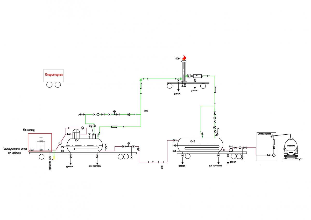
Fig. 2 schematic diagram operating in its own autonomous oil recovery system
Our Contacts
7072 Business Center, Al Shmookh Building UAQ Free Trade Zone, Umm Al Quwain, UAE