Flare Facilities
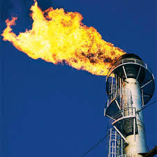
The flare unit is designed for emergency and permanent combustion of petroleum and natural gas or other combustible gases at oil and gas collection, treatment and processing facilities, as well as at oil refineries and chemical plants.

Part of the equipment
Flare units are completed (depending on the requirements of the Customer):
- modern flare heads of domestic and foreign production to ensure smokeless gas combustion (according to environmental safety standards), automatic ignition and combustion control system of domestic and foreign production with a warranty period of 15-30 years;
- flare separators of capacitive and pipe design (pipe gas expanders) of a new type, designed to separate gas from liquid droplets and mechanical impurities, destroy liquid plugs formed in gas pipelines;
- shut-off valves and instrumentation devices, ladders and service platforms.
At the request of the Customer, flare units are supplied:
1) with separate barrels for high and low pressure gas combustion;
2) combined - with two or more trunks;
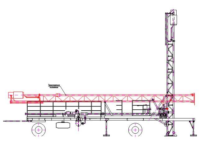
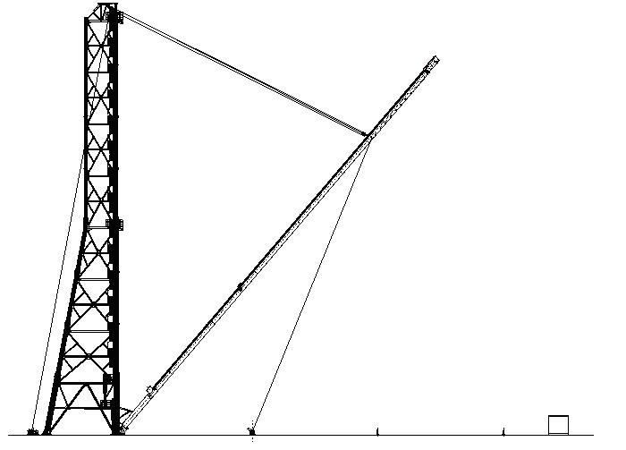
3) complete with lifting mechanisms, to bring the shafts to a horizontal position for repair or replacement of flare heads;
4) complete with lifting mechanisms, for lowering flare heads;
5) surface flare systems of open and closed type.
2) combined - with two or more trunks;
3) complete with lifting mechanisms, to bring the shafts to a horizontal position for repair or replacement of flare heads;
4) complete with lifting mechanisms, for lowering flare heads;
5) surface flare systems of open and closed type.
It is also possible to manufacture mobile flare units on a chassis or frame base.
Below is a range of flare installations.
Below is a range of flare installations.
It is also possible to manufacture mobile flare units on a chassis or frame base.
Below is a range of flare installations.
Below is a range of flare installations.
Designation
Flare installations are designed and manufactured in accordance with TU 3667-035-56562991-2011 (TU 3683-006-56562997-2003).
An example of an entry when ordering products is a flare unit FP-1.0-KhL1 TU TU 3667-035-56562991-2011; combined flare unit CFU-1,0-CP1 TU 3667-035-56562991-2011, where:
FP – flare plant;
CFU – combined flare unit ;
1,0 – amount of discharged gas, million m3/day.;
CP1 – Climatic performance.
Technical details
| Specifications | |
| Working environment | natural, petroleum gas and other combustible gases |
| Gas capacity, thousand nm3/day from 1 to 8000 | |
| Fuel gas consumption for pilot burners, Nm3/h from 1.5?16 | |
| Torch barrel diameter, mm | from 150 to 1400 |
| Flare installation height, m | from 10 to 120 |
| Service life, not less, years | 20 |
Range of produced flare units
| Single barrel flares | |||||||||||||||||||
| Options | Flare Code / Sizes | ||||||||||||||||||
| FP-0,05 CFU-0,05 UFOS-0,05 UFO-0,05 | FP-0,1 CFU-0,1 UFOS-0,1 UFO-0,1 | FP-0,25 CFU-0,25 UFOS-0,25 UFO-0,25 | FP-0,7 CFU-0,7 UFOS-0,7 UFO-0,7 | FP-1,0 CFU-1,0 UFOS-1,0 UFO-1,0 | FP-1,5 CFU-1,5 UFOS-1,5 UFO-1,5 | FP-2,0 CFU-2,0 UFOS-2,0 UFO-2,0 | |||||||||||||
| Amount of discharged gas, thousand Nm3/day | HP | ?50 | 50?100 | 100?250 | 250?700 | 700?1000 | 1000?1500 | 1500?8000 | |||||||||||
| LP | ?40 | 40?100 | 100?200 | 200?400 | 400?600 | 600?900 | 700?2700 | ||||||||||||
| Barrel diameter, DN (mm) | 150 | 200 | 300 | 150 | 200 | 300 | 150 | 200 | 300 | 400 | 500 | 600 | 700 | 1400 | |||||
| Barrel height, m | 10 | 15 | 20 | 10 | 15 | 20 | 10 | 15 | 20 | 20 | 30 | 40 | ?35 | ?45 | ?40 | ?60 | ?40 | ?65 | |
| (in the presence of H2S <8% vol.) | ?30 | ?30 | ?30 | ?30 | |||||||||||||||
Примечания: Стволы высотой до 10 м. поставляются без маршей и площадок.
ВД - высокое давление до 0,2 МПа изб.;
НД - низкое давление до 0,05 МПа изб.
Main types of flare installations
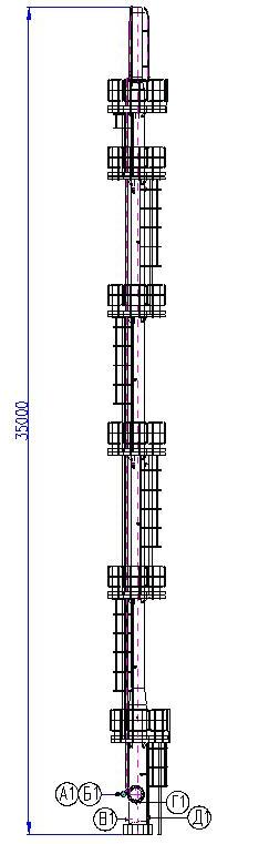
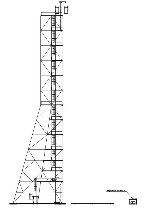
Flare unit FP-0.5-KhL1; DN 500, H=35 m, Qgas=700,000 Nm3/day

| Designation | Purpose | Quantity |
| A1 | Gas to pilot burner | 1 |
| B1 | Waste gas inlet | 1 |
| V1 | Condensate drain | 1 |
| G1 | For instrumentation | 1 |
| D1 | For instrumentation | 1 |
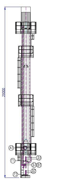
Combined flare unit CFU-0.5-KhL1; DN 250/150, H=20 m, Qgas=300000/40000nm3/day

| Обозн. | Назначение | Кол. |
| А1 | Вход газа ВД | 1 |
| Б1 | Газ на дежурную горелку | 1 |
| В1 | Вход газа НД | 1 |
| Г1,2 | Дренаж конденсата | 2 |
| Д1,2 | Для КИП | 4 |
Combined flare unit CFU-0.5-KhL1; DN 250/150, H=20 m, Qgas=300000/40000nm3/day

Flare unit with drop heads UFO-2.0-KhL1; DN 1000/1000, H=80 m

Chassis flare

Our Contacts
7072 Business Center, Al Shmookh Building UAQ Free Trade Zone, Umm Al Quwain, UAE