Horizontal flare units
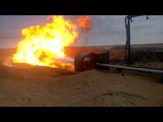
Horizontal flare units (HFU) with remote ignition and control means are designed for burning gases, vapors and liquids during emergency, permanent and periodic discharges at oil, gas and water field treatment facilities of oil and gas fields, chemical, petrochemical and oil refining industries.
Горизонтальные факельные установки разрабатываются и изготавливаются по ТУ 3667-038-56562997-2012.

Characteristics
Climatic version UHL1 with air temperature during operation from minus 60 °С to plus 50 °С.
Depending on the purpose, horizontal flare installations for burning gases and vapors are divided into the following types:
- HFU-B - horizontal flare unit for combustion of gases, purge gases from wells of gas fields, waste gases from wells during plume purge;
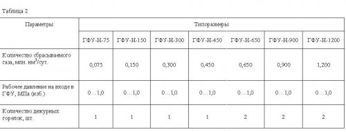
- HFU-H - horizontal flare unit for burning gas effluents from safety valves.
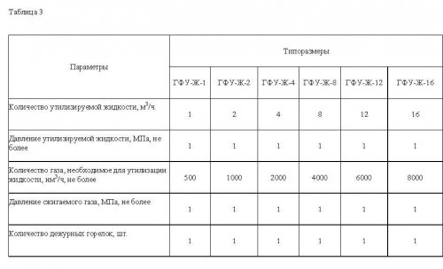
- HFU-L – horizontal flare unit for thermal disposal of industrial wastewater (by evaporation of liquid in the flare with simultaneous combustion of organic and harmful substances);
- HFU-LH - horizontal flare unit for burning liquid hydrocarbons.
- HFU-B - horizontal flare unit for combustion of gases, purge gases from wells of gas fields, waste gases from wells during plume purge;
- HFU-H - horizontal flare unit for burning gas effluents from safety valves.
- HFU-L – horizontal flare unit for thermal disposal of industrial wastewater (by evaporation of liquid in the flare with simultaneous combustion of organic and harmful substances);
- HFU-LH - horizontal flare unit for burning liquid hydrocarbons.
Designation
Examples of product designation entries:
a) HFU-B-100 horizontal flare unit, where:
100 – nominal diameter of the inlet fitting HFU, mm;
b) HFU-H-650 horizontal flare unit, where:
650 is the amount of flared gas, thousand nm3/day;
c) HFU-L-1 horizontal flare unit, where:
1 – amount of utilized liquid, m3/h;
d) Combined horizontal flare unit HFU-L-1-N-75, where:
1 – amount of utilized liquid, m3/h;
75 is the amount of gas burned, thousand nm3/day.
e) Horizontal flare unit HFU-LH-8,3-ХЛ1, where:
8.3 – amount of liquid hydrocarbons (oil) burned, m3/h;
HL1 - climatic version.
Technical details
| Options | Dimensions | |
| HFU-В-100 | HFU-В-150 | |
| The amount of discharged gas, | 2,5 | 5,5 |
| Nominal diameter of HFC inlet fitting, mm | 100 | 150 |
| Working pressure, MPa (ex.) | 0,2…20 | 0,2…20 |
| Number of pilot burners, pcs. | 1 | 1 |
Note:
1) Based on the calculation results, the pressure in the burner should not exceed 6.3 MPa. If this condition is not met, a throttle washer must be installed on the inlet pipeline.
2) The unit is not intended to be used for permanent discharges.
| Options | Dimensions | ||||
| HFU-LH-8,3 | HFU-LH-16,6 | HFU-LH- 33,2 | HFU-LH-66,4 | HFU-LH-99,6 | |
| Amount of burnt liquid hydrocarbons (oil), m3/h | 8,3 | 16,6 | 33,2 | 66,4 | 99,6 |
| Number of burners, pcs. | 1 | 2 | 4 | 8 | 12 |
| Working pressure, MPa (ex.) | 0,8…1,0 | 0,8…1,0 | 0,8…1,0 | 0,8…1,0 | 0,8…1,0 |
| Design pressure, MPa | 1,6 | 1,6 | 1,6 | 1,6 | 1,6 |
| Maximum water cut of burned oil, % | 25 | 25 | 25 | 25 | 25 |
| Required compressed air consumption, nm3/min | 27 | 55,3 | 111 | 221 | 332 |
| Min/Max air pressure, MPa | 0,8/1,0 | 0,8/1,0 | 0,8/1,0 | 0,8/1,0 | 0,8/1,0 |
| Pilot burner, ignition system, flame control | Yes, electric ignition, temperature sensor* | ||||
| Availability of water irrigation | Yes* | ||||


Our Contacts
7072 Business Center, Al Shmookh Building UAQ Free Trade Zone, Umm Al Quwain, UAE