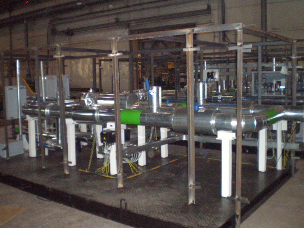
The gas measurement and control system
The gas measurement and control system (GMCS) is intended for automatic operational measurement of the volume of gas transported to gas processing plants, boiler houses, gas power plants and other purposes with the determination of gas quality characteristics (density, pressure, temperature, etc.) and transmission of information to the operator's workstation.
Characteristics
Part of the equipment
The gas measurement and quality control system includes the following equipment:
- a unit for measuring the amount of gas with volume flow meters in directions to consumers, two or more lines (one line is reserve, the second is working);
- temperature and pressure control unit;
- drainage system from pipelines;
- a set of shut-off and control valves;
- block box or base frame;
- control and measuring devices.
Block-boxes are equipped with heating, lighting, ventilation, gas control and fire alarm sensors.
Upon separate request, GMCS is equipped with equipment (instrumentation, shut-off and control valves) of Russian or foreign production, as well as a specialized device for processing data from primary flow, temperature, and pressure transducers.
Upon separate request, GMCS is equipped with equipment (instrumentation, shut-off and control valves) of Russian or foreign production, as well as a specialized device for processing data from primary flow, temperature, and pressure transducers.
Designation
GMCS is available in two versions: blocks of gas metering units of open design - version 1 and placed in block boxes - version 2.
An example of a record when ordering products:
Gas measurement and control system GMCS-0.2-HL1, where:
0.2 is the average daily gas flow rate passing through the GMCS in mln. Nm3/h;
HL1 - climatic version.
Gas quality measurement and control system GMCS-0.2-HL1 average daily gas consumption 200,000 Nm3/day
Technical details
| Working fluid | petroleum and natural gas |
| Working mode | continuous |
| Design pressure, MPa | 1,0; 1,6; 2,5; 4,0 |
| Productivity, million nm3/day | 0.10 to 1.0 |
| Fluid temperature, оC | from +5 to +50 |
| Relative error, % | 0,8 |
| Life cycle, not less, years | 20 |
The range of manufactured GMCS
| Options | Dimensions | |||
| GMCS – 0,1 | GMCS – 0,3 | GMCS – 0,5 | GMCS – 1,0 | |
| Consumption, million Nm3/day | 0,01 - 0,2 | 0,2 - 0,5 | 0,5 - 0,9 | 0,9 - 1,5 |
| Pressure, MPa | 1,0; 1,6; 2,5; 4,0; 6,3; 10,0 | |||
| Temperature, oC | +5 - +50 | |||
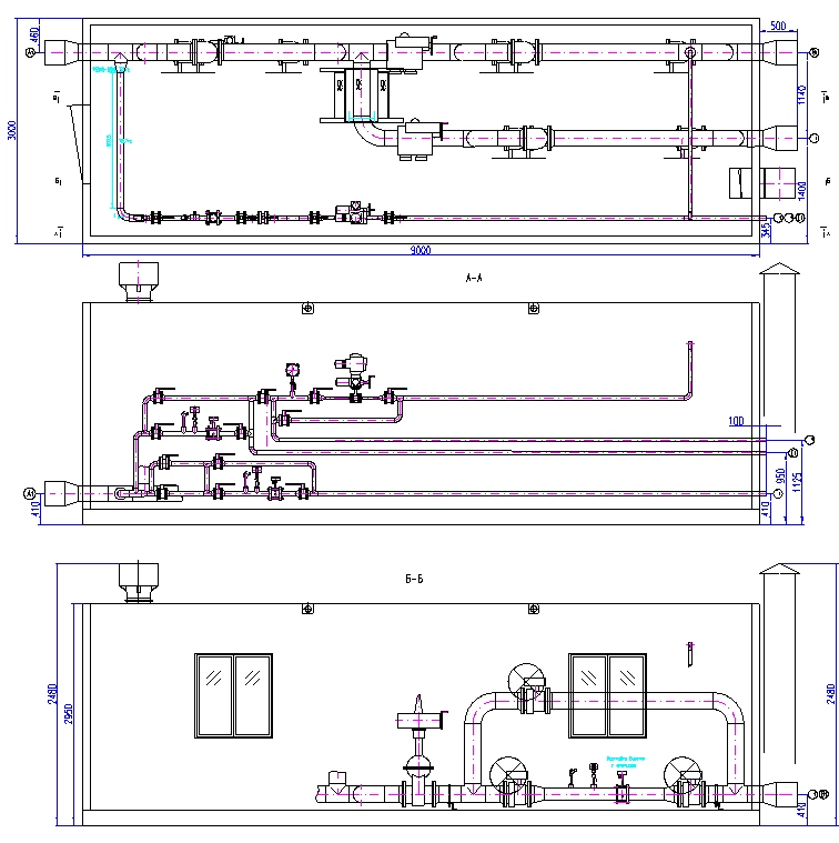
Explication fittings
| Name | Purpose | PN, МPa | Quantity |
| A1 | Gas inlet | 1,6 | 1 |
| B1 | Gas outlet to gas pipeline | 1,6 | 1 |
| V1 | Gas per flare | 1,6 | 1 |
| G1 | Gas to pilot burner | 1,6 | 1 |
| D1 | Gas to maintain pressure in the water buffer tank | 1,6 | 1 |
| E1 | Flare header purge gas | 1,6 | 1 |


Our Contacts
7072 Business Center, Al Shmookh Building UAQ Free Trade Zone, Umm Al Quwain, UAE