The natural gas treatment plant
The natural gas treatment plant (NGTP) is designed to prepare natural gas to the required characteristics.
 Characteristics
| Work environment | natural gas |
| Gas capacity, nm3/day | from 10 000 to 2100 000 |
| Inlet pressure (calculated), MPa, not more than | 12,0 |
| Parameters of the gas flow at the inlet to the plant: | |
| - temperature, °С | – 10 / + 50 |
| - pressure, MPa | 4,0 / 12,0 |
| Parameters of the gas flow at the outlet of the unit: | |
| - temperature, °С | – 25 / + 40 |
| - pressure, MPa | 0,6 / 7,5 |
| Requirements for the quality of gas treatment: | |
| - the temperature of the dew point of gas on moisture, ° C, not higher | –10 –20 |
| - dew point temperature of gas by hydrocarbons, °С, not higher | –5 –10 |
| Ambient temperature, °С | от –60 до +50 |
Technical details
Part of the equipment
1st option (Figure 1):
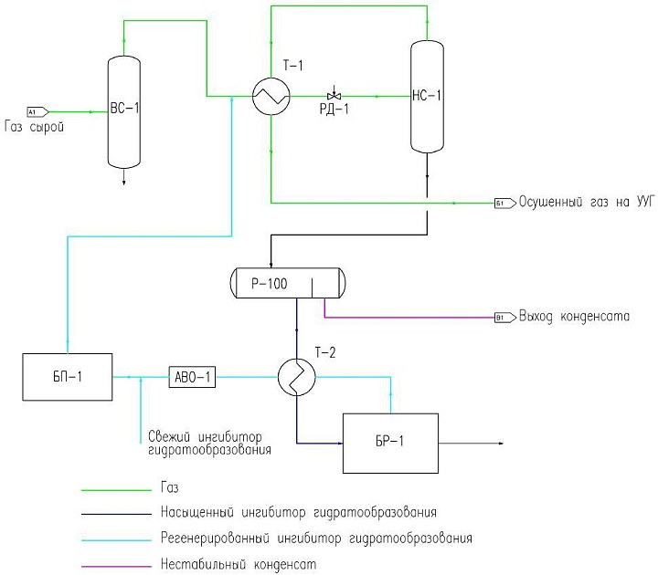
Installation of natural gas treatment by the method of low-temperature separation (LTS).
The structure includes: an inlet separator unit, heat exchangers, a low-temperature separator, a separator, a regeneration unit, a reagent supply unit, with piping, with a set of shut-off, control and safety valves, automation and instrumentation.
2nd option (Figure 2):
Natural gas treatment plant by adsorption drying method.
The composition includes: separators, adsorbers, a furnace, a compressor, an air cooler, with piping, with a set of shut-off, control and safety valves and automation and instrumentation.
Schematic diagram of a natural gas treatment plant using the low-temperature separation method (NGTP)

Picture 1
Raw gas under pressure enters the VS-1 gas separator, where the dropping liquid, the resulting condensate and mechanical impurities are separated, which are sent to the drainage tank.
The gas, freed from the dropping liquid, enters the gas-gas heat exchanger T-1 for pre-cooling with gas, the reverse flow coming from the low-temperature separation.
To prevent the formation of hydrates, an inhibitor of hydrate formation (methanol, diethylene glycol) is fed into the gas before the heat exchanger. Further, the gas is throttled by the RD-1 valve, while cooling due to the Joule-Thomson effect. The cooled gas enters the second separation stage in the gas separator with NS-1, where the condensate with a water-saturated inhibitor solution is separated and sent to the R-100 separator. The dried gas is heated in the T-1 heat exchanger by raw gas supplied for drying to a temperature and sent to a commercial metering unit.
A mixture of unstable condensate with a water-saturated inhibitor solution enters the P-1 separator, where the condensate is separated and sent for preparation. The water-saturated inhibitor solution is heated in the T-2 shell-and-tube heat exchanger by the reverse flow of the regenerated inhibitor and is fed to the BR-1 regeneration unit. The regeneration plant consists of a distillation column installed directly on the cube, in which the liquid is heated by burning gas in a flame tube. Evaporated water is condensed in the air cooler, separated in the collector and discharged into the drainage tank.
The regenerated inhibitor is sent through the T-2 heat exchanger, where it is cooled by a saturated inhibitor flow, and through the AVO-1 air cooler is sent to the supply tank of the BP-1 reagent supply unit. Then the reagent supply unit is returned to the drying unit by pumps and dispensers.
Advantages of low temperature gas separation:
- low capital and operating costs, especially in the initial period of operation in the presence of a free pressure drop;
- in addition to the extraction of liquid hydrocarbons, gas is also dried to the conditions required by the industry standard;;
- NTS installations are quite easy to operate and maintain, thereby it is possible to use technical personnel of average qualification (this circumstance allows the process to be carried out in fishing conditions);
- ease of process regulation and automation in the gas field;
- the possibility of gradual addition and development of technology with a decrease in reservoir pressure and, accordingly, a decrease in the free pressure drop, so that already at the time of design of the installation, various promising options for extending the life of its effective operation can be provided (in particular, through the use of external cold sources, as well as the connection of booster compressor stations).
Disadvantages:
- imperfection of the thermodynamic process of single condensation, while the degree of extraction of the target components from natural gas at a given temperature and pressure in the end low-temperature separator depends only on the composition of the initial mixture;
- during operation, the reservoir pressure decreases (while the content of hydrocarbon condensate in the reservoir gas decreases), so that the "free difference" of pressure on the throttle decreases (the throttle effect is "exhausted") and, consequently, the separation temperature rises - as a result, not only the specific amount, but also the degree of extraction of the target components decreases;
- thermodynamic imperfection of throttle expansion of gas as a refrigeration-producing process compared to turboexpander.
Schematic diagram of a natural gas treatment plant by adsorption drying (NGTP)
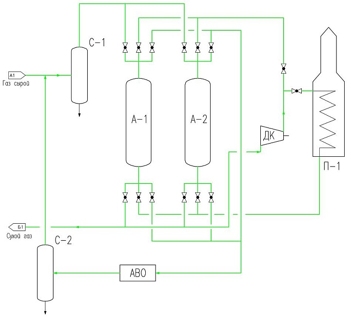
Figure 2
Before entering the adsorbers from the raw gas in the C-1 separator, mechanical impurities and drip liquid are separated. After the separator, the gas passes from top to bottom through one of the adsorbers. The dehumidified gas is discharged into the dry gas collector. The second adsorber at this time is at the stage of regeneration (heating, cooling or waiting).
The regeneration gas is extracted from the dried gas stream and the DC compressor is fed into the P-1 heating furnace and with a temperature of +180-200 ° C is supplied from the bottom up through the adsorber, in which the desorption of water and heavy hydrocarbons is performed. The regeneration exhaust gas is cooled in the ABO air refrigerator and enters the C-2 separator, where condensed hydrocarbons and water are separated from the gas. After C-2, the gas is returned to the C-1 inlet separator and the entire cycle is restarted.
Advantages of adsorption gas drying:
- a low dew point temperature of the dried gas is achieved in a wide range of technological parameters;
- compactness and low capital costs for installations of small productivity;
- change in pressure and temperature does not significantly affect the quality of drying.
Disadvantages:
- high capital investments in the construction of large capacity plants;
- the possibility of contamination of the adsorbent and the associated need to replace it;
- high pressure loss in the adsorbent bed;
- high heat consumption.
Table 1
NGTP parameters
| Options | Product code | ||||||||
| Natural gas treatment plant NGTP | |||||||||
| Dimensions | NGTP-30 | NGTP -100 | NGTP - 300 | NGTP - 500 | NGTP - 700 | NGTP - 1000 | NGTP - 1300 | NGTP - 1500 | NGTP-2000 |
Throughput, thousand st.m3/day | 10 - 40 | 80 - 140 | 140 - 360 | 360 - 580 | 580 -760 | 760-1050 | 1050 - 1350 | 1350 -1600 | 1600 -2100 |
| Gas flow parameters at the inlet to the installation: | |||||||||
| temperature - | –10 / + 50 °С | ||||||||
| pressure - | 4,0 / 12,0 MPa | ||||||||
| Gas flow parameters at the outlet of the installation: | |||||||||
| temperature - | – 25 / + 40 °С | ||||||||
| pressure - | 0,6 / 7,5 MPa | ||||||||
| Requirements for the quality of gas preparation: | |||||||||
| moisture dew point temperature - | –10 –20 °С | ||||||||
the content of mechanical impurities - | no more than 0.001 g/m3 | ||||||||
| mass concentration of hydrogen sulfide - | no more than 0.007 g/m3 | ||||||||
| The volume fraction of oxygen - | no more than 1.0% | ||||||||


Our Contacts
7072 Business Center, Al Shmookh Building UAQ Free Trade Zone, Umm Al Quwain, UAE